Some of the pictures shown here are the steps for assembling the trial frame lenses. If you use sunglasses frames, you must first remove the lower part of the frame so that the eye camera has an unobstructed view of the eye. For the most part, this is pretty intuitive. It's pretty easy to look at a pair of these glasses and figure out how to make them. Apart from the circuits, it's just a matter of gluing some copper wire onto glasses frames and then gluing cameras onto the wire. You want to use malleable copper wire so that you can easily make fine position adjustments.
The circuit(s) to drive the LEDs and the cameras are very easy but it does require some cable-making (which can be a pain). Soldering the LED's together is also a little tricky, but all in all this is a fairly easy project with few components.
First you will want to make a BNC to 'LED-lead' wire. You can either crimp your own (in which case you need a crimping tool, and if you have that, I assume you know how to do this) or else you can take an old scope lead (they're usually BNC) and cut it. In either case, you want to be sure that the 'ground' wire (the copper or lead outer mesh) goes to the negative side of the LEDs and that the 'signal' wire (the inner, insulated portion) goes to the positive side. Same goes for wiring the female jack to the LED driver in the supply box.

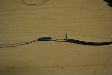
The photo above is the finished product. See the section on cable making below for more details on this stage of the project. You definitely want to do this before mounting the LEDs to the eye camera. Soldering irons next to cameras equals broken cameras.
You can actually use any kind of connectors for this project, but if you use 12V cameras, you may want to distinguish the camera power cables from the LED power cable. The LEDs can catch fire if you run too much juice into them.
By far the trickiest part of this project is soldering the LEDs together and soldering the wires to their leads. The LEDs are small and they must be oriented correctly. Also, they should not be touching -- the only contact should be the solder between the leads. Once this is done, simply super-glue them to a small piece of paraffin or other buffer and glue that to the bottom of the eye camera.
The first step is to glue lengths of 16 gauge copper wire to the top and bottom of the frames. Use super-glue to tack the wire down, let it sit for at least 4 or 5 hours (overnight is best), then apply a coat of epoxy and let that dry (again, overnight). Be careful not to glue together any of the moving parts.
Next, bent the wire into shape so that the cameras can be mounted in a reasonable way. Next, glue the cameras (be careful to get the orientation correct -- there should a mark on the camera indicated which side is 'up') to the wires. Again, let the glue set (this can also be tricky because the camera will want to slide of the round wire) and when it is dry, apply a layer of epoxy to shore it up.
Finally, run the wires (one for each camera plus the cable we made for the LEDs) along the side of the frames. Leave some slack so that you can bend the wire to adjust the camera eye position if need be, then tape it down. I like to apply some heat-shrink on top of the tape -- you don't want this thing getting stuck to someone's hair
That's it! You are done. It should look like this at the end.
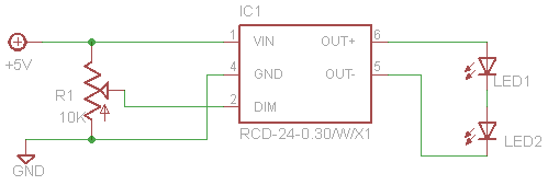
The power supply for this is very simple, and I will assume that the reader can follow a circuit diagram and breadboard this circuit. As has been mentioned, if you use 12V cameras, you must convert the 5V power supply to 12V. In that case you have two circuits to build.
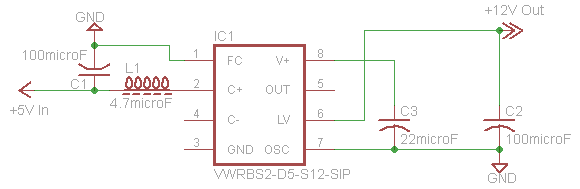
Note that the pin labels are meaningless. The pin numbers are correct, however. For a better diagram of this circuit, you may consult the VWRBS2-D5-S12-SIP data sheet
If your cameras operate at 5V, then you can simply wire the output jacks in series with the input jack (which is what we show here).

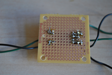
When you have built the circuit(s), it's time to get a drill out and make some holes for all your jacks. To do a really nice job, I recommend a drill press, but if you don't have one you can certainly do it with a hand drill. Be very, very careful when you do this! Start slow and be methodical. It is easy to slip and drill a hole through your hand if you aren't being cautious.
It's a good idea to test the jacks before soldering them up. Sometimes you get a dud. To do this, simply plug it into a 5V power supply (we recommend a USB to 5mm barrel cord -- which can be bought or constructed with an old USB cable) and whang one your multimeter. The outer ring is connected to the pin on the inside of the jack so your red probe on this and the black one on the central lead should give 5.34 volts.
Next it is time to do the wiring. I find it easier to do the wiring once all the jacks are mounted, but you have to be careful. I include some pictures rather than a diagram since it is so simple.


In the case of the 5mm jacks, the green wires always carry +5V and are always connected to the left most pin on the 5mm jack (the outer ring). The black is always the central pin and the output jacks should be wired in series to make a complete circuit.
The BNC output is a little different. The green is the same, but the black is not technically ground. It is the output of the LEDs which flows back to the LED driver. In any case, it is wired to the 'ground' ring of the BNC jack, even though this isn't actually connected to the ground plate.
At this level they should not ever get hot to the touch. Then close up your box and track some eyes!
You will need to make some male to male 5mm barrel cables to go from the output of the power supply to the camera power inputs. This is fairly simple. We use Low noise coaxial wire which is a little tricky. You have to be careful not to pierce the inner 'signal' wire or else you will run the danger of shorting it to the ground mesh. It is also a little tricky to manipulate the mesh and solder it cleanly to the outer ring of the barrel jack.
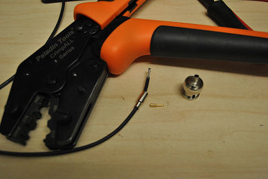
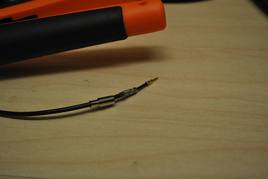
First strip the outer part of the cable exposing the inner wire encased in wire mesh. MAKE SURE TO SLIDE THE JACK CASE ON THE CABLE BEFORE SOLDERING THE JACK ON!!!! Then pull the wire mesh back and expose a small length of the inner copper wire. I like to set the jack in something convenient (one of the slots in my crimper was just right) then flow some solder into the inner ring, filling it. Then simply re-heat the solder and slide the little bit of exposed inner wire in.

Be careful when crimping the outer ring, you don't want to pierce the inner wire. You'll also want to dab some solder to ensure a connection between the mesh and the outer ring lead.
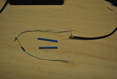
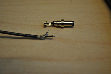
The same basic strategy goes for making the cable that goes from the LED leads to the BNC jack. You will want to expose exactly (or nearly exactly) 1.5cm of the inner cable and strip .5cm off of that. This will ensure that the BNC jack fits correctly on the cable. Peal the mesh back all the way around the outer wire.
Now, stick the central pin (usually this comes separate) in something, and fill it with solder. Then re-heat and insert the exposed inner wire just as we do with the 5mm barrel. The rubber casing should lie flush if youhave measured your cuts and strips carefully. Also, when the inner wire is inserted into the BNC sleeve, it should lay flush with the non-stripped portion of the outer wire. Then it is time to crimp (most satisfying) and since the mesh is pealed back on the outer part of the BNC, you don't have to worry about soldering that to anything. The crimping will make a connection

This cable terminates not in another jack, but a pair of wires that we solder to the LED leads (see above). Again, be careful not to create any short circuit in the cable. You should not be afraid of using heat-shrink to keep the wires isolated from one another.