Download the latest version of the software from ftp://sccn.ucsd.edu/pub/software/LSL/Mobi_Utils. This software assumes that you have an eye tracker with one scene camera and one eye camera.
Plug in and turn on the eye tracker.
Open GazeStream.exe.
If your cameras are plugged in correctly and support Microsoft Direct Show (almost all cameras do) they will appear under "Video Device". Select the eye camera from the "Video Device" menu and click "Use as: Eye Camera" If you are using multiple eye trackers, you can put an identifier in "Stream Identifier" to be able to tell the data streams from the various eye trackers apart.
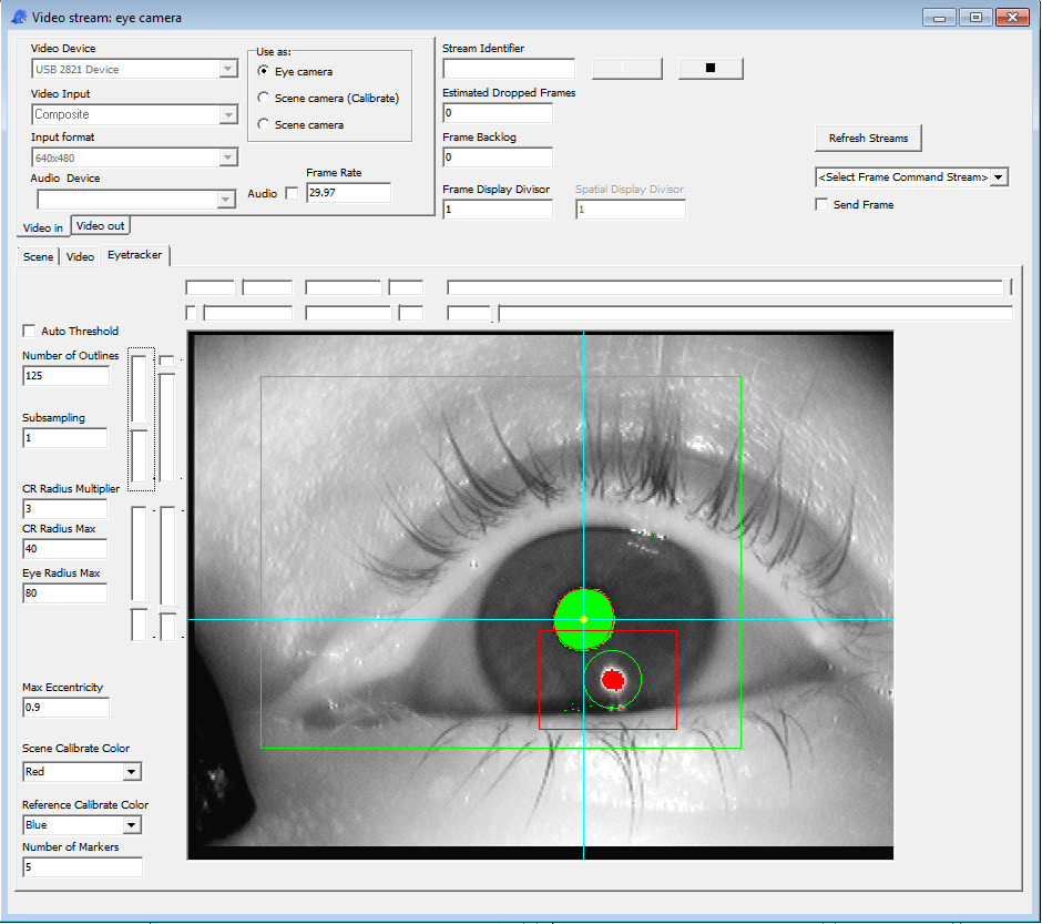
Click the green arrow. Video from the eye camera should appear.
If the eye is not illuminated, check the electrical connections to the LEDs. The LEDs are infrared, but when working they visibly turn red. If the eye is not in the center of the field of view, reposition the eye camera by firmly pinching the copper arm against the tracker frame and bending the copper arm to the correct position. The super glue that holds the eye tracker together is fairly sturdy, but it will not resist significant force.
In the field of view, there are two boxes, a red box and a green box. The green box determines the field of view for pupil tracking, and is controlled with the inner set of sliders. The red box determines the field of view for cornea reflection tracking and is set with the outer set of sliders. The two sliders on the upper right determine the thresholds (with the outer one being cornea reflection and the inner one being pupil).
Checking "Auto Threshold" will direct the threshold to be set automatically. This is useful for variable lighting conditions.
"Number of Outlines" determines the number of non-contiguous green spots below threshold that "Auto Threshold" attempts to create by changing the threshold. Generally a fairly large number is more stable than a small number.
The threshold will not be automatically lowered such that the eye fit gets larger than "Eye Radius Max." This prevents a situation that can occur when the threshold rises to the point that the iris is fit instead of the pupil.
"Max Eccentricity" provides a cutoff for non-circular objects (such as shadows near the eyelid). A value of 1 means that all non-circular objects will be accepted, while the lower the value is the more circular it must be.
"Subsampling" reduces the number of points that are checked for being below threshold. This will decrease processing load, but will make the results less accurate.
The purpose of fitting the cornea reflection is to remove its influence on the pupil fit. Specifically, around the cornea reflection is a cornea reflection area of influence marked with a green circle. Any points within the cornea reflection area of influence will not be included in the pupil fit. Otherwise, the pupil fit fits bad data when the subject is looking in the direction of the LEDs and errors are introduced. Do not worry if the cornea reflection disappears or is fit poorly when the subject is looking far away from the LEDs. Unlike many other eye trackers, the cornea reflection is not used for a reference point, it is only a source of noise that must be removed.
"CR Radius Multiplier" determines how much larger the cornea reflection area of influence is that the fit of the cornea reflection.
"CR Radius Max" determines the maximum size of the cornea reflection area of influence.
Typically, it is possible to choose these parameters such that tracking is rarely lost.
Open another instance of GazeStream.exe.
Use the same value in "Stream Identifier" that you used for the eye camera.
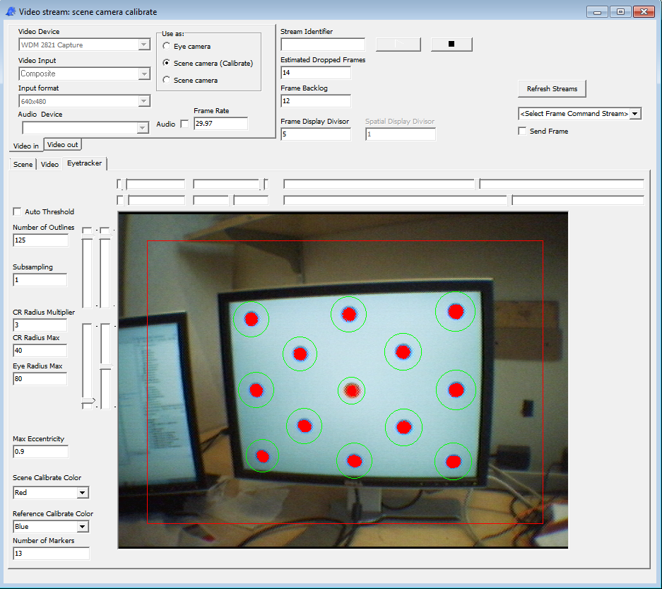
Change "Number of Markers" to the number of markers in each calibration pattern. Typically, the three monitor setup uses 5 markers, and the one monitor setup uses 13 markers.
Click Play.
Jump to to the next section to learn how to make the calibration pattern appear on the screen.
After the calibration pattern appears, use the sliders on the upper right to adjust the thresholds. By default, the target marker is red (this is what the subject will focus on) and there are blue background markers. If the markers do not appear red and blue in the scene camera view, then it will be necessary to adjust the lighting. Most cameras include automatic gain, contrast, and color adjust and do not always make the correct choices. This can be corrected in many cases by placing a large white sheet behind the monitor, or adjusting the background color of the calibration pattern. This is done by setting the "Calib Background" colors in EyeCalibrator.exe, closing the calibration window (with escape) and then clicking "Load Monitor Position" and "Calibration Window" again.
The inner slider adjusts the target threshold, and the out slider adjusts the background threshold. All the markers must be tracked for accurate calibration, as the calibration procedure uses the full pattern to measure the location of the camera with respect to the markers. See below for what it should look like when all the markers are being tracked.
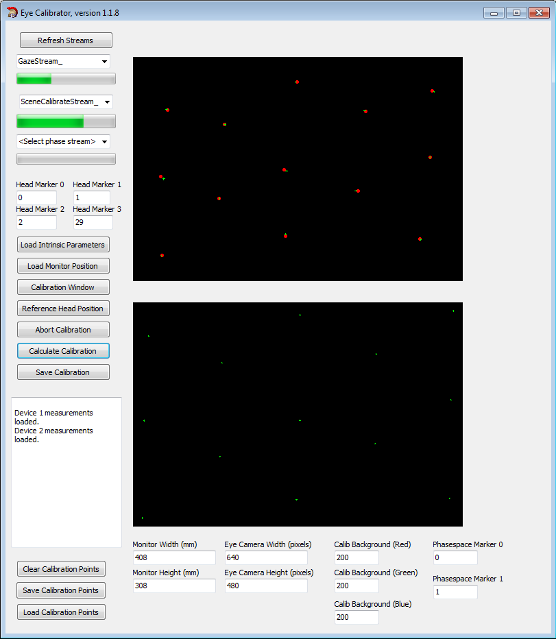
Open EyeCalibrator.exe. Select "Gazestream_StreamID" from the first drop down and "SceneCalibrateStream_StreamID" from the second drop down. Select nothing from the third drop down. Ignore the head marker fields.
Click "Load Intrinsic Parameters," and select the appropriate parameter file for your camera and lens. An example file is here. These parameters follow those from OpenCV. A proper file should have been included with your eye tracker. If it was not, see the end of this document for a procedure to generate it.
Click "Load Monitor Position" and select a proper file. An example file is here. The parameters here are fairly intuitive. Note that the "device" numbers can be any positive integer, do not necessarily match those of the Windows OS, and are used to reference the calibration area throughout the application. Typically a calibration area will match a physical monitor.
Click "Calibration Window" and select a calibration pattern file. An example file is here. The first column must match the device number from the monitor position file. The second number gives target locations, ranging from 0,0 in the lower left and 1,1 in the upper right. If there are multiple devices in the calibration pattern file, there will be multiple calibration areas used in the calibration. This can be useful in multiple monitor setups.
At this point, go back to the Scene Camera instance of GazeStream.exe and finish the setup.
Ignore "Reference Head Position."
After all the markers are being tracked in the Scene Camera Instance, ask the subject to follow the red spot. Each time the subject looks at a new spot, adjust the parameters for the eye camera and scene camera if necessary and then hit the spacebar. After one second, the target spot will move. Check in the eye calibrator window that the error bars are small. The top window tracks the eye position fit. The bottom window tracks the scene camera position fit. To retake a data point, hit 'B'. Note that the keyboard will be unresponsive unless EyeCalibrator.exe is the focused window. The subject is free to move their head between looking at different spots.
After the subject has looked at each of the points, the calibration window will close. Click "Calculate Calibration". The green crosses are the data and the red points are the fits. In a good fit, these nearly overlap, as shown below. Click "Save Calibration".
Go back to the Scene Camera version of GazeStream.exe. Click "Use As: Scene Camera". Click "Load Calibration." Select the file that you just saved in EyeCalibrator.exe. You should now see a spot that tracks the gaze in the scene camera view.
The eye tracker can be coregistered with phasespace. This allows us to determine the location of the subject's gaze in phasespace coordinates. The first step is to measure the phasespace location of any monitors used in calibration. This can be done before the subjects arrive. It does not need to be repeated unless the calibration monitors move or the phasespace calibration changes.
Configure phasespace with at least one phasespace marker.
Use the lab streaming layer (LSL) phasespace driver to convert the phasespace data into an LSL stream.
Open Hotspots.exe.
Select the phasespace stream from the upper left drop down.
Next, it is necessary to mark the locations of each of the monitors in phasespace coordinates. For each position, click, "Add," select the correct phasespace sensor #, click "Capture," then "Done." In order to make sure that you are detecting the correct phasespace marker, it is useful to cover it, click "Capture", then uncover it and click "Capture" again. If you are holding the correct marker, its position will be 0,0,0 when covered, and valid numbers otherwise. After you click "Done", the locations will show up in the text window towards the bottom.
Do this for each position: top left, top right, bottom left, bottom right, for each monitor of interest. The order matters. Be careful to hold the emitting part of the LED directly above the corner of the emitting part of the screen.
Click "Fill" in the lower right. The central area will fill with the marked locations.
Click the "Screen" button in the top row. A new form will appear. The IDs will be 1,2,3,4. If you click "Screen" from a lower row, it will count up from that row instead. "From Sensor" defaults to "e", which is eye position. "To Sensor" defaults to "g", which is gaze position. These behave as virtual phasespace markers, and describe a vector from eye to gaze to indicate where the subject is looking. "From Sensor" and "To Sensor" can be changed to positive integers to track conventional phasespace markers. "Device" is used to track which monitor is which. "Monitor Depth" gives the distance between the phasespace marker location when held at the corner of the screen and the actual light-emitting part of the screen. "X", "Y", "Width", and "Height" give the Windows coordinates of the calibrating monitor in pixels. Once all the parameters are correct, hit "Done" Repeat for every monitor that will be used in calibration or that the subject will be looking at during the experiment.
The results will appear on the "Screen" tab. Eye position is represented at "-2", and gaze position is represented as "-3".
It is wise to test that the screens are described correctly in phasespace coordinates. This should be done without eye tracking. Change "From Sensor" to "1" and "To Sensor" to "2" or some other conventional phasespace marker ID. Click "Open Displays". In this mode, an invisible line will be drawn from marker "1" to "2", and a spot will be put on the screen where the line intersects with the screen. Line up the two markers with your eye and check that the spot appears in the correct place. When being careful, it is helpful to check each corner of each screen.
To close the windows, hold down the Windows key and press tab until you select Hotspots.exe. Click "Close Displays". Click "Save Config" to save the hotspots calibration.
Later, after the eye calibration (see the next section) is done, select the gaze camera stream from the "Reading eye data from:" drop down.
Click "Load Calibration" and select the eye calibration file.
Under the "Screen" tab, change the "From" to 'e' or '-2' and the "To" to 'g' or '-3'.
Click "Open Displays" and confirm that the eye position is tracked properly by holding up a finger and asking the subject to follow it.
To close the windows, hold down the Windows key and press tab until you select Hotspots.exe. Click "Close Displays".
Open EyeCalibrator.exe. Select "Gazestream_StreamID" from the first drop down and "SceneCalibrateStream_StreamID" from the second drop down. Select the phasespace stream from the third drop down.. There should be four active phasespace LEDs attached to the subject's head. Put the ID numbers of these markers in the "Head Marker" fields.
Click "Load Intrinsic Parameters," and select the appropriate parameter file for your camera and lens. An example file is here. These parameters follow those from OpenCV. A proper file should have been included with your eye tracker. It is planned to make the procedure for generating this file apparent, but this has not yet been done.
Click "Load Monitor Position" and select the hotspots configuration file that you created in the last section.
Click "Calibration Window" and select a calibration pattern file. An example file for a three monitor setup is here. The first column must match the device number from the monitor position file. The second number gives target locations, ranging from 0,0 in the lower left and 1,1 in the upper right. If there are multiple devices in the calibration pattern file, there will be multiple calibration areas used in the calibration. This can be useful in multiple monitor setups.
At this point, go back to the Scene Camera instance of GazeStream.exe and finish the setup.
Once the target markers are being tracked, ask the subject to be still for a moment, and click Reference Head Position. In the text window the distance between the scene camera and the target marker will be printed. If this number is not reasonable, check to make sure that all of the markers (both calibration spots and phasespace markers) being tracked correctly and that all of the parameters files are correct.
After the reference head position has been accurately measured, ask the subject to follow the red spot. Each time the subject looks at a new spot, adjust the parameters for the eye camera and scene camera if necessary and then hit the spacebar. After one second, the target spot will move. Check in the eye calibrator window that the error bars are small. The top window tracks the eye position fit. The bottom window tracks the scene camera position fit. To retake a data point, hit 'B'. Note that the keyboard will be unresponsive unless EyeCalibrator.exe is the focused window. The subject is free to move their head between looking at different spots.
After the subject has looked at each of the points, the calibration window will close. Click "Calculate Calibration". The green crosses are the data and the red points are the fits. In a good fit, these nearly overlap, as shown below. Click "Save Calibration".
Go back to the Scene Camera version of GazeStream.exe. Click "Use As: Scene Camera". Click "Load Calibration." Select the file that you just saved in EyeCalibrator.exe. You should now see a spot that tracks the gaze in the scene camera view.
Go back to Hotspots.exe and check the phasespace dependent eye tracking as described at the end of the last section.
While most of the calibration is dependent on the subject, there is a set of parameters that are associated only with the scene camera. These measure distortion and scaling of the scene camera. Unfortunately, the procedure for generating these parameters still half-baked, so the procedure is a bit obscure and manual. You will need to download this application. Unzip it, and edit myNewOpenCV/Debug/VID5_in.xml. Typically BoardSize_width is 7, BoardSize_Height is 6, and Square_Size is 25 (mm). This corresponds to a calibration chessboard (which you will need to make or acquire) with 8 x 7 squares (7 x 6 intersections) of 25 x 25 mm for each square. Save changes and run myNewOpenCV/Debug/myNewOpenCV.exe. This will open a window which will tell you where out_camera_data.xml will be saved, and should open a window that stars a preview mode on your default camera. If the wrong camera is shown, unplug the wrong camera and restart the application. Hold the chessboard in front of the camera and The press 'g' to start acquiring. It is best if the chessboard fill the full field of view of the camera and you move it around while acquiring. After 25 successful frames, a new out_camera_data.xml will be output and a measure of the error will be output to the terminal. Open the out_camera_data.xml file (from the location indicated in the terminal). The interesting numbers are in the <Camera_Matrix><data> block. This is a 3x3 matrix that needs to be copied to the Intrinsic Camera Parameters File. file under cameraMatrix. Note that the format of the numbers is slightly different. You will also need to copy the <Distortion_Coefficients><data> vector to distortionCoeffs. You can then begin the calibration procedure described above using the new intrinsic camera parameters file. The first time you use it, it is good to check to make sure that it can properly find the distance between the scene camera and the target spot. This number appears in "Distance to Calibration Point (mm)" in EyeCalibrator.exe. If it is wrong, it is necessary to either redo the intrinsic parameters calibration or manually adjust the scale factor in the camera matrix. This is controlled by the first and the fourth numbers in the cameraMatrix, which must match each other. It is very important that the range is determined correctly.
Contact mgrivich at ucsd dot edu or dmedine at ucsd dot edu for more assistance.